We hear the phrase that water is the universal solvent. Why? So many materials dissolve in water due to its unique molecular structure. So it does not seem like a fluid to be used in a hydronic heating system made of many different materials. Water does have many advantages as a heat transfer material. It Read more
Heating & Cooling

We hear the phrase that water is the universal solvent. Why? So many materials dissolve in water due to its unique molecular structure. So it does not seem like a fluid to be used in a hydronic heating system made of many different materials. Water does have many advantages as a heat transfer material. It is cheap, safe, easily acquired, has a wide liquid temperature range, and is generally non-toxic.
With water coming from so many different sources worldwide, it can contain many different minerals. It is the wide combination of these minerals that water gathers as it flows through our aquifers that needs attention.
Many of the common minerals found in water will cause issues in hydronic systems. The hardness of the water, and minerals that fall from solution, are the most common concerns. As the minerals precipitate out, they can stick to and coat the surfaces of our boiler heat exchangers, for example. This coating forms until enough build-up reduces the heat exchange and the metal of the heat exchanger breaks down. A classic example is what you see when you drain an old tank-style water heater. Some of the material that can be found in tap water cause further concern…like chlorides.
Boiler and tank manufacturers are now listing the most harmful minerals as well as acceptable levels. Calcium, magnesium, chlorides, and sulfates are commonly listed. The ph level is also required to fall within a range, something like 6.6 and 8.5 according to one boiler specification.
Failure to maintain the proper water chemistry can cause loss of efficiency, noise, wear, premature failure, and most important to the consumer, lack of warranty.
So the industry needs to first get some training on what to look for, how to measure levels, and what to do with water that does not meet the quality required to assure warranty coverage.
Most agree that starting with good quality water is one key. It is possible that the water in your town is of sufficient quality. But if you are not testing, you are guessing. Know also that water quality in an area can vary season to season. One of the most noticeable changes in water quality can be linked to the road deicing chemicals used. Back in the day, rock salt, maybe blended with sand, was the go to deicer. Nowadays chloride blends are being used in may states. Chlorides have a wider melt range, and can be applied as a liquid. They often get applied before a snowstorm, or icing condition as a proactive measure.
Guess where these chlorides end up? In our water supplies, via lakes, rivers, and even well sources. Many water sources have been seeing a spike in chlorides. States like Wisconsin and Minnesota have been monitoring this carefully as the aquatic life in their thousands of lakes and rivers are being affected by the elevated chlorides, as well as the flora and fauna.
There is a fairly simple fix for water that is not of sufficient quality for use in hydronic systems. Both deionizing and chemical treatments are available to help bring water back to a hydronic-friendly heat transfer fluid.
Flush your systems. Consider a hydronic detergent to rid the system of oil, flux, dirt, etc. Test the water for the final fill, and treat as required, or haul quality water from another source.
You will be hearing more about boiler water quality as manufacturers of boilers, tanks, pumps, valves, etc. start reexamining warranty returns that have been compromised by fluid quality. It will be a tough conversation to have with a home or building owner if an expensive component fails prematurely due to fluid quality and the warranty is refused.
 Hot Rod is currently the training and education manager for Caleffi North America. He owned his own contracting company, Show Me Radiant Heat & Solar, Rogersville, Mo., having been a plumbing and heating contractor since 1978.
In 2012, Johnson Controls, Inc. published a white paper I wrote titled “Solar Thermal Energy: The Time Has Come.” In it, I stated “Solar heating, often overshadowed by photovoltaic systems, is the most cost-effective on-site renewable energy resource. It presents a vast opportunity for public and private organizations to save on fossil fuels, cut costs Read more
In 2012, Johnson Controls, Inc. published a white paper I wrote titled “Solar Thermal Energy: The Time Has Come.” In it, I stated “Solar heating, often overshadowed by photovoltaic systems, is the most cost-effective on-site renewable energy resource. It presents a vast opportunity for public and private organizations to save on fossil fuels, cut costs, and reduce carbon emissions”. What’s changed? These facts are truer today.
In the white paper I discussed the technical potential for solar water heating in the United States valued at about one quadrillion Btu of energy savings per year, worth billions of dollars in energy cost savings and 50 million to 75 million metric tons of carbon dioxide emissions. (The Technical Potential of Solar Water Heating to Reduce Fossil Fuel Use and Greenhouse Gas Emissions in the United States. National Renewable Energy Laboratory, Technical Report NREL/TP-640-41157, March 2007)
These figures may be merely theoretical, but they illustrate the vast possibilities for solar thermal technology to displace fossil fuels, counteract climate change, and save building and business owners and industrial processes money. (Hundreds of thousands of dollars)
For those of you who only know solar energy as Photovoltaics (PV) there is another solar technology that has the potential to significantly reduce Green-House-Gas emissions often referred to as the other solar “White Meat” basically ignored by most of the State and DOE, Federal Energy and R&D programs except Solar Thermal Electric Generation (CSP). Common uses of the other white meat or I should say the other solar technology include: swimming pool heating, boiler water preheating, domestic water and space heating, air conditioning, and high temperature heat for a wide range of commercial and industrial processes such as Industrial Process Heat (IPH).

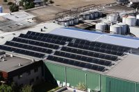
De Bortoli Wines Australia
A recent study titled “Initial Investigation into the Potential of CSP Industrial Process Heat for the Southwest United States” (Initial Investigation into the Potential of CSP Industrial Process Heat for the Southwest United States Parthiv Kurup and Craig Turchi, National Renewable Energy Laboratory, Technical Report NREL/TP-6A20-64709, November 2015) by Parthiv Kurup and Craig Turchi of the National Renewable Energy Laboratory looked at the technical potential and the applications of the different CSP technologies based on solar delivery and facility temperature requirements.
The assessment for California indicates a technical thermal energy potential of almost 23,000 TWhth/yr. significantly more than the estimated demand of about 48 TWhth/yr for the industrial sectors in California that utilize mostly natural gas for IPH. The report validates the contributions and opportunities for commercial Solar Industrial Process Heat (SIPH) plants which is becoming a growth industry and opportunity to re-establish the contributions of solar thermal heating.
The report also states “After significant interest in the 1970s, but relatively few deployments, the use of solar technologies for thermal applications, including enhanced oil recovery (EOR), desalination, and industrial process heat (IPH), is again receiving global interest. In particular, the European Union (EU) has been a leader in the use, development, deployment, and tracking of Solar Industrial Process Heat (SIPH) plants.

De Bortoli Wines Australia
In the nonresidential sector, users of solar thermal technology include hotels, hospitals, prisons, restaurants and cafeterias, government buildings, universities and schools, athletic facilities, manufacturing plants, and laundries.”
These are all growth markets which are not limited to Europe and the Southwest US. These applications are in every community and city in the nation. Industry, Universities like the University of California Merced Solar Lab and National laboratories continues development of high temperature concentrating technologies that are capable of temperatures from 230 F to 350 F or higher and the US DOE are investing in R&D for advanced Concentrating Solar Power (CSP) technologies up to 1200 F.
In today’s renewable energy market Solar Thermal Collection Systems provide lower Levelized Cost of Energy (LCOE) than any other solar energy technology due to technological efficiencies and cost advantages, therefore making a better business case than any other technology for broader market acceptance. When the LCOE, the relatively low US market penetration, and manufacturing demand needs of the Solar Thermal market are collectively considered, a tremendous investment opportunity is revealed.
Most high temperature thermal technologies in the market, require large surface areas and tracking systems adding significant hardware and O&M costs.
These concentrating technologies also need direct beam radiation which limits their applications to the desert and dry environments and generally have significant production losses in diffused radiation which makes up the majority of the US and all of the Caribbean. Some of the Evacuated Tube collectors which can be mounted on either the roof or ground use both Direct Normal irradiance and Global Horizontal irradiance to generate the efficiencies for high temperatures without tracking. And they generating up to 400oF temperatures for use anywhere in the US or Caribbean.
The solar thermal collection technologies are field-proven. In the past 15-20 years, product research and development and improved manufacturing have created a new generation of simple, reliable, efficient solar water heating systems. Modeling tools are available to predict system performance, costs, energy savings and return on investment based on local sun and weather conditions.
At present, solar thermal technology faces some headwinds, but longer-term trends appear to work in its favor. For the time being, the price of natural gas—the main fuel solar heating displaces—are at low levels as hydraulic fracturing (fracking) operations dramatically increase domestic supplies.
At the same time, commodity prices for glass, copper and aluminum used in solar thermal collectors are rising as the economy improves. There is also a shortage of contractors trained in solar thermal installations, and the same financing obstacles exist as for solar thermal as for many types of renewable energy. Finally, prospective users of solar thermal energy may not fully understand it or appreciate its versatility and value.
All these conditions are likely to be temporary. Fuel and commodity prices are cyclical by nature. In 2008, prior to the great recession, natural gas prices stood near historic highs. Prices may rise again as the U.S. exports more gas, as utilities add gas-fired peaking power plants and replace older, polluting coal-fired power plants used for base load with smaller gas turbines. Also with potential to tip the scale are the increased production of liquefied natural gas (LNG) for export and wider acceptance of compressed natural gas (CNG) as a fuel for buses, taxis, cars, and a wide assortment of fleet vehicles.
Growing numbers of states and utilities offer incentives and rebates for renewable energy installations. In addition, renewable portfolio standards (RPS) or some kind of Renewable requirements have been passed in about 40 states, requiring utilities to derive specified percentages of their power from renewable sources of those about 16 allow solar thermal to meet the goals.
Electric utilities, municipalities and some state legislatures have developed incentives and marketing campaigns using photovoltaics to meet RPS requirements. As I just said, the 16 States that include Solar Water Heating, 13 states allow Solar Space Heating and 11 states include Solar Industrial Process Heat to qualify for the RPS. Much more could be done to develop Solar Thermal incentive programs for residential, commercial and industrial applications.
A simple and reliable metering technology would enable conversion of solar thermal energy to its kilowatt-hour equivalent, allowing solar water heating or cooling to count toward RPS compliance, as well. A growing number of states now allow solar thermal projects to qualify for utility incentives or may qualify for renewable energy credits (RECs) under their RPS programs.
The California Energy Commission, again leading the way to Energy Independence, Renewable Energy and Energy Efficiency to reduce carbon emissions has issued a RFP for Advanced Water Heating System Demonstrations, Advanced HVAC and Building Envelope Demonstrations, Integrated Natural Gas System Demonstrations, and Applied Research Strategies for Appliances, Zero Net Energy Buildings, and Codes and Standards.

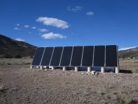
UC Merced XCPC array
The State of California has set aggressive goals demonstrated by this RFP for increasing energy efficiency in buildings and reducing greenhouse gas emissions. In addition, they say recent events at Aliso Canyon in Southern California emphasize the urgency in identifying, demonstrating and deploying technology solutions and strategies that can reduce natural gas consumption in these building sectors while overcoming other barriers associated with using new and/or emerging natural gas reducing technologies.
This is a big step in accelerating the applications and demonstrations of advanced solar thermal heating technologies. And a big win for the “other white meat” let’s hope it’s a start to increased funding and market deployment for Solar Heating and SIPH.
More opportunity than meets the eye
The principle behind solar thermal energy is simple: A solar collector absorbs heat from the sun, and fluid warmed by passing through tubes in the collectors is distributed to the appropriate system. The basic technology has existed for more than 100 years, and systems have been proven to last more than 25 years—longer than a conventional water heating systems—at a fraction of the life-cycle cost. Solar collectors can be installed anywhere on a facility with adequate access to unobstructed sunlight. Estimates show that tapping the United States’ full potential for domestic and commercial solar water heating could:
• Save 578 billion cubic feet of natural gas per year—2.5% of the nation’s usage.
• Save 35 billion kWh of electricity per year, just under 1 percent of U.S. consumption.
• Prevent 52 million metric tons of carbon dioxide emissions annually, equivalent to the emissions from 13 coal-fired power plants or 9.9 million cars. (3 Smart, Clean and Ready to Go: How Solar Hot Water Can Reduce Pollution and Dependence on Fossil Fuels. Wisconsin Environment Research & Policy Center, March 2011.)
The most widespread solar thermal application is water heating. A typical residential-sized solar water heating system produces 7 to 10 kWh per day, or 3,400 kWh per year, depending on local conditions and type of collector and the system design. On average, for each such system installed in place of an electric water heater, 0.5 kW of peak demand is deferred from the utility’s load. When a utility solar water heating program like Hawaii’s has thousands of solar water heaters installed displacing electricity, the demand reduction is measured in megawatts.
So, what’s the problem in Florida? I refer to it as the land of the electric water heater and little potential for natural gas expansion. It is also a state with a huge coastline, barrier islands and water shortages that are being ignored by the pro-business electric utility legislature. It’s been documented many times in the past, solar water heating in Florida is a net revenue loss to the electric utilities. Isn’t less electricity generation using fossil fuels one of the solutions to climate change and rising sea levels? Who has the most to lose; the electric utility industry, the coastal businesses and homeowners or possibly the whole Florida economy? What are the long term plans for rising waters and drinking water shortages? That is a stupid question. Why make plans when you deny there is a problem. Climate change plans would have a negative impact on future political contributions for those in office who support studying the problem.
A commercial solar water heating system with 500ft2 of collector will displace the hot water generated by a small natural-gas-fired boiler, generating 2,281 therms per year and offsetting more than 26,825 pounds of CO2. On a larger scale, solar thermal energy creates economic development and local jobs in manufacturing, installation, operations and maintenance.
Commercial SIPH plants will provide the necessary energy for:
• Industrial Process Heat
• Desalination,
• Food and Beverage processing,
• Solar Cooling & Refrigeration systems,
• Oil & Gas extraction,
• ORC or Stirling electric generation
Space heating
Similar to solar water heating systems, these systems generally use more solar collectors, larger storage units, and more sophisticated designs. Concentrating or tracking solar thermal technologies are required to meet space heating loads. For the higher temperatures needed for hydronic forced air heating systems (180oF) temperatures, Flat Plate collectors and most Evacuated Tube systems cannot consistently operate at those temperatures.
Cooling
Here, solar heating systems are coupled with absorption chillers and use a thermal-chemical sorption process or ammonia to produce air-conditioning without electricity. The process is like that of a refrigerator except that there is no compressor. The absorption cycle is driven by a thermal transfer fluid—heated water or glycol mixture—from the solar collector. Water cooled to about 44 degrees F runs through copper piping, and forced air passing over the piping produces air conditioning. Options include replacing electric chillers or injecting chilled water generated by a solar absorption chiller into a building with a large cooling load.
Despite the high potential, solar thermal capacity in the United States lags behind much of the world. For example, on a per-capita basis, the nations’ ranking has dropped from 35th to 50th globally in solar water heating (excluding swimming pools)(Werner Weiss and Franz Mauthner, International Energy Agency, Solar Heat Worldwide: Markets and Contributions to the Energy Supply 2008, 2010.) – although such installations increased and grew by 10 percent in 2009,(Solar Energy Industries Association, U.S. Solar Industry Year in Review 2009, April15, 2010.) and increased by another 5 percent in 2011 despite a slow economy with historically low natural gas prices.(SEIA/GTM Research U.S. Solar Market Insight 2010 Year in Review.) Bad news is the solar heating industry is experiencing a steep downturn in the residential solar heating market not just in the US but the industry is down globally by an average of 15% since 2013 as reported by the SH&C Program of the International Energy Agency (IEA)
Most (94%) of the solar systems installed worldwide provide domestic hot water (small-scale and large-scale systems). However, megawatt-scale solar thermal applications for district heating and solar heating and cooling in the commercial and industrial sector is a growing market. The two largest solar thermal systems are in Denmark and supply heat to district heating networks. The two largest solar cooling systems are in Singapore and the United States. And, the world’s largest solar process heat system is installed in Chile at a copper mine.
Jobs
The number of jobs in the fields of production, installation and maintenance of solar thermal systems was estimated to 730,000 worldwide in 2014. The worldwide turnover of the solar thermal industry was US$ 24 billion.(Solar Heat Worldwide, IEA Solar Heating & Cooling Programme, May 2016: Franz Mauthner, Werner Weiss, Monika Spörk-Dür) The Solar foundation has recently documented the growth of the US solar Industry and a majority of those new jobs are in the PV industry but imagine the thousands of new jobs a robust National Solar Thermal Initiative would create.
Catching the sun
Many organizations fail to benefit from solar thermal energy largely because they do not know the many possibilities it offers. There are three basic levels of solar thermal energy:
• Low-temperature (80 to 100 degrees F) for purposes such as swimming pool heating and boiler water preheating.
• Medium-temperature (100 to 160 degrees F), largely for domestic/service hot water heating and space heating.
• High-temperature (180 to 350+ degrees F) for industrial processes and air conditioning and hybrid HP desalination.
Evacuated tube systems do the same basic work as flat-plate collectors but perform better in cold climates when not buried under snow because the vacuum inside the tubes reduces heat loss from conduction and convection. The basic structure includes a glass tube made of borosilicate glass that allows sunlight to pass through, and a black-coated copper or aluminum absorber inside the tube.
The performance advantage over flat-plate systems is not significant in warmer climates, except where users desire very hot water and are not buried in snow, for a commercial process.(It is proven that flat-plate collectors perform better than evacuated tubes in areas with snow in winter, as the insulated evacuated tube does not re-radiate heat to melt the snow off the collector.
The typical heat loss of a flat-plate collector will melt snow and start generating energy on clear days, Typically, a flat-plate collector is the first thing on a roof to become free of snow.) Installed costs are about the same as or higher than for flat-plate systems that have been around for more than 100 years.
Micro-trough systems, use parabolic reflectors to focus sunlight on a receiver, can achieve temperatures from 160 to 350+ degrees F. They are used mainly for space heating, industrial process, and solar air conditioning (when coupled to absorption chillers). Micro-troughs depend on direct-beam radiation as in the desert southwest and track the sun in a single axis (east to west) for maximum heat generation.

XCPC or External Concentrating Parabolic Collector is the new technology in the market, manufactured by Artic Solar in Jacksonville, Florida. The patented XCPC Non-Imaging Concentrating Collector is a non-tracking high temperature collector capable of +350oF temperatures for SIPH applications and more importantly for Advanced HP integrated Desalination systems as demonstrated by WaterFX for cleaning up subsurface agricultural waste water in California. (Pilot demonstration of concentrated solar-powered desalination of subsurface agricultural drainage water and other brackish groundwater sources, Matthew D. Stuber, Christopher Sullivan, Spencer A. Kirk, Jennifer A. Farrand, Philip V. Schillaci, Brian D. Fojtasek, Aaron H. Mandell October 2014) Imagine if clean water was made available to the 1 in 10 people in the world without access to clean water. Solar thermal is making progress and is here to stay. The XCPC is proving to be a game changer.
Flat-plate or evacuated tube systems actually perform better in areas with hazy sunlight or diffused radiation such as the Gulf Coast. Knowing the technologies and their limitations is important in selecting the right technology for the job.
When is solar thermal attractive?
Solar water heating systems can be highly cost-effective in facilities that have constant or even intermittent hot-water demands. Other forms of solar heating can be economical in a wide range of settings, depending on heat requirements, local climate and sun conditions, and other factors.
Nonresidential solar heating systems generally require professional design and sizing. A key step is to determine the heat or cooling load to be met. In particular, sites like manufacturing plants, food processing, commercial laundries, hotel kitchens and restaurants require higher temperatures and appropriate sizing. Determining the feasibility of solar thermal for a given application is largely a straightforward site audit process.
Once the audit is complete, commercially available modeling tools can accurately predict the cost of the system, the thermal output, and the economic benefit, measured in time to achieve positive cash flow. Most off-the-shelf solar collectors have been tested by an independent laboratory and certified by the International Association of Plumbing and Mechanical Officials (IAPMO) or Solar Rating and Certification Corporation (SRCC) to specify what their energy output should be under specific local sun conditions. If a solar collector doesn’t have IAPMO or SRCC Certification, don’t buy it.
Advances in thermal or seasonal storage will have significant impacts on Net-Zero Energy buildings. There are low cost methods to integrate seasonal storage into buildings which will improve the economics and significantly reduce the energy required to heat buildings and homes in the winter. Years ago heating buildings with large solar thermal systems in the winter caused problems in the summer. Too much heat, stagnation and over-heating were common problems. Drainback system designs solved the over-heating issues but the economics were upside down using the system only in the winter. Today, new technologies allow us to heat the building in the winter and drive absorption chillers for cooling or ORC electric generators in the summer. These systems can easily couple to thermal storage if necessary so the economics for year-round solar thermal systems are significantly improved but unfortunately under-utilized.
Making the move
Opportunities for solar thermal energy are available to almost any organization. A company with expertise in solar energy can help evaluate the possibilities, select the most appropriate technology for the site, model the costs, savings and cash flow.
It is prudent to select a project partner that understands not only solar energy but also how to integrate a thermal system with the existing building heating system, cooling system, or process, and with the building or process controls. A well-qualified supplier will also have access to innovative financing programs and will be able to help secure rebates and other incentives from utilities and federal and state governments.
Solar thermal is a highly cost-effective way to deploy renewable energy, reduce long-term operating costs, and make progress toward sustainability, reducing GHG or green building goals.
 William T. Guiney is President of Artic Solar, Inc., a certified Veteran Owned Small Business in Jacksonville, Florida. He has close to 34 years’ experience in the solar industry as a contractor, educator, distributor and manufacturer, has provided renewable energy and energy efficiency training programs, and is an instructor for solar thermal energy systems at the North Carolina Clean Energy Technologies Center and the Florida Solar Energy Centers. He has served on the solar thermal technical committee of the North American Board of Certified Energy Professionals (NABCEP) and was chair of its Thermal Entry Level Committee. Guiney is currently a serving on the advisory council for the Solar Heating & Cooling Alliance (SH&C) of the Solar Energy Industries Association (SEIA).
Lochinvar Celebrates 30yrs of Power-Fin® Commercial Product Line The pioneer product of efficient heating experiences a milestone in July 2016 Tennessee-based Lochinvar, LLC is celebrating the 30th anniversary of its industry-changing Power-Fin product line this July. “As a company, we are proud to celebrate the 30th Anniversary of the Power-Fin product line. This product line Read more
Lochinvar Celebrates 30yrs of Power-Fin® Commercial Product Line
The pioneer product of efficient heating experiences a milestone in July 2016
Tennessee-based Lochinvar, LLC is celebrating the 30th anniversary of its industry-changing Power-Fin product line this July.
“As a company, we are proud to celebrate the 30th Anniversary of the Power-Fin product line. This product line transformed the industry and elevated Lochinvar into a leadership position,” said Mike Lahti, vice president of sales, marketing and business development. “Our industry has seen a lot of change over the last 30 years, and at the time of its introduction, the Power-Fin product established a new standard of performance and design.”
Developed in 1986 from Lochinvar pioneer William Vallett Sr.’s vision for a high-efficiency water heater and boiler, the Power-Fin product was the first of its kind and remains the model of efficiency today. With four original models ranging from 250,000 to 1,000,000 Btu/hr., it hit the mark in an industry hungry for high efficiency products. The Power-Fin series was the first commercial product to offer a variety of new technologies and features including:
- Direct vent sealed combustion technology
- Self-diagnostic, removable panel
- Multiple venting options
- Copper-finned, vertical heat exchanger
- Low-mass with a small footprint
- Only boiler in its class that was able to fit through a 36-inch door
“The Power-Fin products created consumer demand and acted as a catalyst for the company’s growth in the 80’s and 90’s which prompted the move to our state-of-the-art new headquarters in 2001,” says William Vallett, Jr., chief executive officer. “Lochinvar’s leadership position in the commercial water heater and boiler business was rooted in the success of the Power-Fin product line.”
The original Power-Fin series played a role in heating water for applications such as nursing homes, restaurants, schools and more. The unique features of the product allowed for the installation of a gas appliance in an area where traditional gas appliances may not be installed due to space constraints in the building.
“Starting with the Power-Fin product line in 1986, we were able to provide something that other companies weren’t focused on, efficiency and footprint,” says Dan Sheko, national sales manager. “Now, 30 years later, we are proud to have continued that tradition and provide some of the highest efficiency products on the market.”
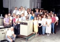
The Power-Fin product was the first to commercialize fan-assisted technology and to this day, still impacts the way engineers think about venting, gas pressure and volume. Lochinvar’s Power-Fin line revolutionized both Lochinvar as a company and the industry as a whole. At the time of its creation, Lochinvar had approximately 30 employees, four of whom are still with the company.

1986 Lochinvar group with the original Power-Fin
Thirty years since its creation, the Power-Fin product remains one of Lochinvar’s best-selling items. The product continues to evolve, with new “Built-in Advantages,” including expanded burner modulation and the advanced SMART SYSTEM™ operating control. Look for a new Power-Fin product line announcement coming soon.
In response to a growing interest in residential and commercial solar energy systems, IAPMO first developed and published the Uniform Solar Energy Code in 1976. Just like the 2009 and 2012 editions of this code, the 2015 Uniform Solar Energy and Hydronics code (USEHC) was developed using IAPMO’s American National Standards Institute (ANSI)-accredited open consensus Read more
In response to a growing interest in residential and commercial solar energy systems, IAPMO first developed and published the Uniform Solar Energy Code in 1976. Just like the 2009 and 2012 editions of this code, the 2015 Uniform Solar Energy and Hydronics code (USEHC) was developed using IAPMO’s American National Standards Institute (ANSI)-accredited open consensus process, and is unique in that it is both a Code and an American National Standard.
The 2015 USEHC is developed to govern the installation and inspection of solar, hydronic, and geothermal energy systems as a means of promoting the public’s health, safety and welfare. Published previously as the Uniform Solar Energy Code, the 2015 edition adds significant provisions concerning hydronic and geothermal systems (see sidebar, below).

This comprehensive, consensus IAPMO/ANSI Code provides a single source reference for the installation, use or maintenance of radiant, hydronic, geothermal and solar systems. It can have a significant positive impact by leading to the increased utilization of these high efficiency and renewable energy systems. It also raises the bar for the industry, much of which has been unregulated for many years. Uniformity will be a significant benefit, as will the opportunity for fewer callbacks on problem installations and satisfied consumers. No other model code published today specifically addresses the design and installation of solar, geothermal, hydronic and radiant heating and cooling systems.
“This new code provides a single, comprehensive standard for hydronic heating and cooling systems. It will improve the clarity and consistency of hydronic systems design and operation to everyone in the industry,” said Mark Hudoba, director, Heating and Cooling, Uponor.
“Having minimum standards assures that consumers get a solid-performing hydronic heating or cooling system,” said Hudoba.
Who benefits from widespread acceptance and adoption of the USEHC?
- Contractors — The provisions of the USEHC help eliminate confusion and controversy on the part of Authorities Having Jurisdiction (AHJs) by establishing consensus guidelines for the application of radiant and hydronic technologies in the built environment.
- Manufacturers, Engineers, Architects and Contractors — Have pertinent design and installation topics, previously addressed in multiple codes or regulations, now available in a single ANSI consensus standard. (Note that some aspects of system installation may need to comply with mechanical or other codes applicable in the local jurisdiction).
- End Users — Understanding that the sharing of knowledge that the USEHC has been developed by subject matter experts in accordance with vetted system design criteria and accepted construction techniques.
RPA Setting the Bar High
The overall goal of the Radiant Professionals Alliance (RPA) has always been one of raising the bar for professionals, while instilling confidence in the consumer and government that properly designed, installed and maintained hydronic systems will and can provide the highest degree of comfort and efficiency.
The RPA is committed to contributing professionalism to the entire hydronics/radiant industry and promoting such systems as the most viable path to energy savings and comfort for the end user. Many provisions of the 2015 USEHC concerning radiant heating and cooling applications have not appeared in model codes before; RPA’s involvement in the development of relevant language ensures that state-of-the-art design and construction principles are considered.
It has taken years of diligent effort by RPA and the collective best minds in the industry. When the decision was made to create a Hydronics Code, RPA was successful in creating a code committee representing all facets of the industry: manufacturers, suppliers/distributors, contractors, installers, and government officials/inspectors. The RPA Code Committee spent more than a year compiling relevant information, even from foreign countries, and molding it into a working document.
“We find ourselves on the brink of bringing this whole program to fruition. We are getting prepared to help our members of this industry to move forward, and put hydronics into the wheelhouse of every consumer, architect and engineer in North America, and it is critical that we have to include the installation and design entities as a part of our program. The RPA always has been, and will continue to be, about education. Not just contractors education, but education of the end users, as well as the design teams involved in putting these buildings together, and the people in the field enforcing these codes,” said Mark Eatherton, executive director, RPA, which is in the process of developing educational curriculum that will explain the many nuances of the code, and provide drawings and explanations for purposes of interpretation. These classes will be offered to RPA and IAPMO members at a discount over non-members. A formal announcement will be made once these classes come online.
Although RPA did offer voluntary guidelines in the past, there was very little information available to the industry or the consumer in a meaningful, useable format regarding design criteria and best practices. Much of the content of the RPA guidelines was in more of a “should” configuration, as opposed to mandatory code required language, using words like “shall.”
When the possibility arose that the RPA Code document could become part of an American National Standard, the document was submitted into the process, a balanced ANSI Committee was created, and the document was further refined over an additional three years, with experts from every facet of the industry contributing countless hours, worth literally millions of dollars, to the effort.
Having an accredited American National Standard brings the ultimate credibility to the USEHC.
Local Enforcement
A code is only as good is the enforcement in the field. The RPA has begun teaching and working with the code enforcement officials in itx efforts to bring their knowledge base of these mechanical systems up to speed so that they are much more comfortable performing their job in the field.
Some people believe that the code will dictate exactly how they must install their system. This is not correct. The code establishes a minimum standard, and in most cases where the contractors have been receiving training, guidance and direction from competent manufacturers, they are already installing systems that exceed the minimum standards. It is those jobs that are being performed by unqualified, untrained personnel that will be required to change their ways. Our bottom line goal is to increase the consumers’ confidence about the safety, reliability, efficiency and comfort associated with the proper design and installation of these wonderful systems and make the installing contractors job of meeting the AHJ’s requirements quicker, smoother and easier.
The availability of this code means that in jurisdictions where it is adopted, a single source for many provisions affecting the installation of these systems will be available to contractors and AHJs.
“I expect two primary impacts on AHJ’s. First, many AHJ’s will look to familiarize themselves with the code in an effort to improve their ability to inspect and approve systems. Code information and training opportunities for AHJs can be found on the IAPMO website: http://www.iapmo.org. An electronic version of the code can be viewed at http://epubs.iapmo.org/USEHC/. Second, the code will make it easier for AHJs to enforce the code due to the consistency of proper system design and installation,” says Hudoba.
It will provide residential and commercial consumers the assurances and protections of a viable, quality installation in an understandable format. Inspectors and AHJs receive the guidance and protections of a model code developed in a consensus process from the industry. “The clarity and consistency that the code provides will reduce the number of improperly designed and ill-performing systems that are installed, thereby enhancing the overall professionalism of the hydronics trade,” said Hudoba.
Designers and contractors should know that subject matter experts specializing in each of the technologies addressed in the USEHC invested significant personal time in the development of the code in an effort to include accurate and complete provisions.
The code will provide experienced installation contractors with verification that what was taught to them by competent manufacturers and the RPA are good recommendations to follow, and that their work will exceed the codes minimum requirements.
“As a former working mechanical contractor, I can speak from personal experience that the only way we typically find out that the code has changed is when we violate the code and find ourselves on the wrong side of the enforcement official. That is a very expensive, non-productive method of learning, but one that you won’t soon forget. We are trying to educate our members in advance so that when their jurisdiction adopts these codes that they will not be caught flat footed,” said Eatherton.
The Federal Fingers
There have been rumblings from within the industry about government overreach and about contractors who are worried about the government’s involvement in building a hydronic code. Yet, it isn’t the government developing the code, it is the industry that is responsible for helping to develop the codes. “It is the government that will be enforcing the code, and any code is only as good as the AHJ who is enforcing the code. We have already started training the AHJ’s, and this will only make the good contractors job easier. The inspectors will now have the ability to know what is right, and what is wrong, and the right ways of performing these jobs,” said Eatherton.
A contractor who has received good and regular training from a recognized, competent manufacturer is most probably not going to have to make any major changes in their operations. They are already in compliance with the provisions of the code. It is the unlicensed people who are out there doing all of the wrong things that end up giving our industry a black eye that will be the focus of this code, not the well trained, experienced contractors.
As a code/standard development organization, IAPMO is constantly looking for more involvement from our industry members, regardless of where they fall in the food chain. Everyone from the consumer all the way up to the manufacturer, and every entity in between has open access to the process, and we invite their participation in the development of these open consensus codes and standards.
Manufacturing members must be included as a part and parcel of this whole process. Many of the manufacturers have helped in populating the many different technical committees involved in the development of the applicable codes. “We will be leaning heavily upon our manufacturer members in all aspects of the deployment of this code and the associated education and certification standards that were developed in conjunction with the code. We intend to certify our manufacturers facilities, as well as their instructive personnel to bring the whole program together. We’ve already begun negotiations with numerous manufacturer members, and they are in full support of our efforts,” said Eatherto
Additional Standards
To increase customer awareness and confidence, ASSE International is developing a Hydronic System Installer and Hydronic System Designer National Standard and certification program. It is our intent that the Authority Having Jurisdiction will recognize this certification and require it as minimum criteria to allow contractors and designers to perform work in their jurisdiction. This program is expected to be released in 2016.
The RPA is developing an Instructive Training Manual, and a Best Practices Manual. These two items will be used going forward to ensure that we have provided the contractors and designers with the tools necessary to ensure proper and appropriate applications of these mechanical systems. It will take the designers and installers through the steps necessary to ensure that the delivery method correlates with the energy source. Using staple up tubing with a ground source heat pump has its limitations, and we must make certain that everyone with skin in the game understands the limitations and appropriate application of these and all hydronic heating and cooling systems.
The RPA has been heavily involved in the development of the ASSE/IAPMO/ANSI Series 19000: Hydronic Systems Professional Qualifications Standard. This Standard is a program to certify expert hydronic heating and cooling systems designers and or installers, as well as solar thermal installers. This is a very stringent program, requiring proof of active field service as well as approved course materials before the applicant will be allowed to sit for the test. Our hope is that the AHJ’s around the country will recognize this program for the value that it brings to the industry, and we hope that it will become a minimum requirement for people who are applying for licenses to do hydronic and solar thermal work in their jurisdiction. This will have some mandatory educational provision that the RPA already has available to the public thorough our educational partner, HeatSpring. These courses can be previewed at https://www.heatspring.com/partners/radiant-professionals-alliance.
SIDEBAR
Solar & Hydronics Code Provisions
Key provisions of the 2015 USEHC and changes from the 2012 edition include:
- New hydronics chapter provides:
– radiant heating and cooling
– snow melt systems
– minimum requirements for the capacity of heat sources
– heating appliances and equipment
– piping, joints and connections
– system controls
– space heating
– steam systems
– auxiliary systems
– installation, testing and inspection of hydronic systems
- New condensates waste and control provisions for condensate-producing equipment and appliances
- New alternative engineering design provisions
- New provisions for accessibility, attic and underfloor installation, and roof installation of appliances and equipment used in solar energy, hydronic, and geothermal energy systems
- New solar thermal provisions, such as materials, solar collectors, freeze and overheat protection, drainback and thermosiphon systems, and pressure testing
- New geothermal energy systems chapter provides minimum requirements for groundwater systems, ground-heat exchanger design, heat exchangers, heat pumps, distribution design, and the installation of geothermal energy systems
- New duct systems chapter provides minimum requirements for ducts used for conveying air for heating and cooling of spaces
- New electrical provisions for the installation of solar photovoltaic systems based on NFPA 70-2014
I recently started up the heating system for our family’s cabin in Northern Minnesota. Yeah, recent as in a couple weeks ago when our heating systems were still needed overnight and even some days. The heating system is a hybrid of panel radiators and radiant ceilings with a few feet of baseboard in the mix Read more
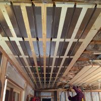
I recently started up the heating system for our family’s cabin in Northern Minnesota. Yeah, recent as in a couple weeks ago when our heating systems were still needed overnight and even some days. The heating system is a hybrid of panel radiators and radiant ceilings with a few feet of baseboard in the mix.
The radiant ceiling is for the main living area [slab on grade, ground level]. It was selected over all other emitter options because it provided us with the most flexibility of room layout, furniture placement and available wall space for cabinets, windows etc. I should also point out that the concrete slab was poured in the 80’s and is in no condition to consider removing for in-slab radiant installation given the added cost to the project and extended timeline that would create. Oh, and I’m not a huge fan of engineered panel systems that install over existing floors; at least not over concrete given the added downward load and modification to finished floor height.
We simply went the old fashion route and built the ceiling panels with 1x boards, aluminum heat transfer plates and PEX tubing (MR PEX, O2 Bariirer 1/2″ tubing & MR PEX S.S. Radiant Manifolds).
I was able to take some quick videos and photos of parts of the install and finished product. Take a look below and please continue reading as I’d like to cover a few myths with my own explanations about why radiant ceilings are a good alternative to radiant floors and are often overlooked.
The following are excerpts from a previous blog post I shared here on The Hub.
Radiant ceilings can easily operate at surface temperatures up to 100 F, delivering in excess of 55 Btu per square foot. Since ceilings are typically constructed of gypsum based sheet rock, they offer very little resistance to thermal transfer. Unless interior designers regress to the 1960’s and resume putting shag carpeting on the ceilings it’s likely the output of the ceiling won’t change during the life of the home. In any discussion of radiant ceilings and comfort, there seems to be some ingrained misunderstandings of the concepts. Someone will say that “heat rises, therefore you’ll have a hot head and cold feet”. Not true. Heat doesn’t rise. Hot air rises. In radiant systems objects of mass are heated without heating the air. In fact, there is typically more hot air rising with a radiant floor than with a radiant ceiling. This is because air molecules that come into contact with the radiant ceiling already occupy the highest strata. In radiant floors, the cooler molecules sink and come into contact with the warm floor surface and rise as their density changes with heat, driving the convective forces that cause stratification. Under normal conditions neither radiant floors nor radiant ceilings heat the air to an uncomfortable level like in forced air systems.
Another myth about radiant floors and ceilings involves the surface temperatures that are achieved. Just as the beach sand absorbs the overhead rays of the sun, radiant ceilings warm the floor. There are no cold floors in radiant ceiling projects.
Installing the radiant ceiling PEX tubing. #boilerguy
A video posted by Aune (@awe_knee) on

Kitchen and patio Door area. Notice not all of the ceiling requires tubing installation to meet the heat load requirements.

The same area of the kitchen & patio door as shown above in the thermal image.
As always, if you’ve got something to add to this article or have any questions for its author please do not hesitate to do so in the comment section below. Thanks for your time!

Initial firing of boiler on call for heat, <1 minute run time.

Approximately 3 minutes upon boiler firing

<10 minutes after firing boiler