I will always preach that a successful cast iron water boiler installation begins with proper planning. I worked for an oil company for 20 long years, and nine years of that I was a service manager. During this time, I came across many problematic jobsites. I would evaluate the installation issues and try to figure out where the problems had started. This knowledge has greatly helped me as a Training Manager for U.S. Boiler Company. Now, after 40 years in the heating business, I know how important proper boiler installation planning really is for reducing the number of problem jobs and expensive callbacks. In fact, planning is much easier than you may think …
- Proper boiler sizing. Complete a thorough heat loss calculation. Do not fall into the trap of oversizing the boiler because you sized it based on the old boiler size or you measured the connected radiation load, and never allow the customer to talk you into a larger boiler than needed. Today, with physically smaller boilers and less water volume, oversized boilers will short cycle more than ever. Increased short cycling means higher maintenance, higher fuel costs, and higher installation costs.
- Follow the boiler Installation & Operation (I&O) Manual. Be sure to follow one of the suggested near boiler piping options listed in the manual. The boiler tapping may not have to be the same size as the manifold piping. Use the flow charts for pipe size. You can pipe the boiler the same size as the tapping, or in some cases, use smaller piping dependent on the heat loss requirement. When the heat loss is known and the proper boiler size is chosen, you may be able to use smaller air separators, expansion tanks, and piping. You can use the following as a guide to size the boiler and system piping:
- 3/4” pipe = 40,000 BTU’s @ 4 – 5 GPM (gallons per minute)
- 1” pipe = 70,000 BTU’s @ 7 – 8 GPM
- 1-1/4” pipe = 160,000 BTU’s @ 16 – 18 GPM
- Bypass piping. Bypass piping is discussed briefly in the I&O manual. We cannot continue to install modern cast iron boilers the same way we used to install boilers with larger water volumes. When needed, a bypass system should be installed to protect the boiler. There are primary/secondary piping and circulated bypass options, both of which we will discuss later in this article.
The bypass system discussed in the manual is called a “boiler bypass” and is always installed the same size as the supply and return headers. When adjusted, the water flow through the boiler is slowed so the water spends more time in the boiler. This allows the boiler temperature to increase faster and decreases the possibility of boiler condensation. This means that some of the system return water is bypassed around the boiler and enters the supply beyond the boiler. I know what you are about to say. “Well, that will cool off the supply water going to the homes heating system!” That is correct, but it is not a problem. This is what I call a “poor man’s outdoor reset.”
The system will run quieter and the system water temperature will increase slowly until the radiation outputs enough heat to satisfy the thermostat. The colder it gets outside, the hotter the system supply water temperature will be. When the valve placement is installed as shown in the manual, we can easily adjust the ΔT through the boiler. Simply put, leave the bypass valve open and adjust the flow through the boiler with either valve located on supply or return pipes below the bypass pipe to slow the flow and force more water through the bypass. Partially close one of these valves and check the ΔT through the boiler. You will need a minimum of a 20°F rise. If this is a large water volume system, like cast iron radiation, increase the ΔT through the boiler to 35 – 40°F ΔT.
Quick Tip: If the bypass is hotter than the return pipe, the flow is backwards and you have piped a system bypass as opposed to a boiler bypass. Follow the piping in the manual to verify correct installation.
- Primary/secondary piping option. Primary/secondary piping utilizes hydraulic separation so that the water flow from system pumps do not affect boiler pump flow. This allows us to reduce the flow through the boiler to heat the water faster and heat the water to a higher temperature without affecting the flow in the system. In other words, we can have a higher flow in the system and a lower flow in the boiler. We still want a minimum of 20°F rise through the boiler, and for higher water volume systems we want a higher ΔT near 35°F – 40°F.
- Variable speed bypass pump option. To have the best boiler protection, install a variable speed bypass pump with a temperature sensor. This will change the speed of the pump to obtain the proper return water temperature. We offer a variable speed bypass kit with instructions for gas water boilers. This will protect the boiler in a high-water volume system or radiant in-floor radiation application.
Quick Note: My concern, and the reason for the above discussion of boiler protection from condensation, is excessive water flow through the boiler and slower temperature increase. I have experienced multiple boiler installations where the ΔT through the boiler is less than 20°F. In fact, I have witnessed some as low as 8°F. Lower ΔT’s are a result of excessive flow, possibly caused by the number or circulator sizes installed on the system. So, what is the minimum flow rate on cast iron water boilers? Look in the I&O manual under specifications and find the DOE heating capacity (MBH) of the boiler. For instance, the Series 3 model 304B has an input of 105k MBH and a DOE heating capacity of 88k MBH. Divide the DOE output by 10,000 to discover the maximum flow required by the boiler. If your flow exceeds that number, the ΔT will be less than 20°F. You can use this hydraulic formula to determine flow rate through the boiler.
- Avoid short cycling. Short cycling is caused by lower water flow, or higher ΔT. Higher ΔT may mean that the circulator is to small, the boiler is oversized, or the valves not adjusted properly. Generally, the minimum boiler flow should be half (but not limited to) of the maximum boiler flow.
Boiler Flow Formula:
Q/(500*ΔT) = Flow
Q = DOE Heating Capacity
Let’s put some numbers to that formula. Let’s assume that a boiler has a ΔT of 15°F. The Series 3 model 304 (referenced above) has a DOE heating capacity of 88,000.
88,000/10,000 = 8 GPM. This is the maximum flow required by the boiler. Divide this in half to get the minimum boiler flow. In this case, it would be 4 GPM.
Now, back to the formula.
Q=88,000
ΔT = 15°F
88,000/(500 * 15) = Flow
88,000/7500 = 11.7 GPM
The flow is almost 4 GPM higher than the maximum flow the boiler should have. This tells us we need to achieve a 20°F ΔT, which means less flow through the boiler. Why do we have to much flow? There are oversized pumps or to many pumps. Using a bypass or primary/secondary strategy above, we can easily correct the flow through the boiler.
- Vent the boiler properly. If the boiler is chimney vented, the local and federal codes apply. A chimney liner may be required. If the unit is direct or power vented, the manufacturer dictates the venting according to the certifications obtained during testing. Since this article applies to cast iron water boilers, a sidewall vented boiler requires AL29-4C vent pipe. No plastic!
- Outdoor air. I like to use outdoor air as much as possible to verify enough combustion air. Plus, there is less chance of contaminated air.
- Gas pressure. Check the incoming gas pressure and the manifold (outlet) pressure with other gas appliances running. Check all safeties. Finally, always complete a combustion check.
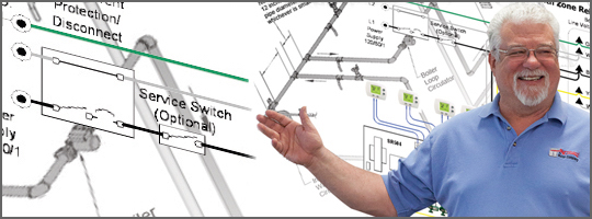 Ron Beck is Outside Technical Advisor and Manager of Training for U.S. Boiler Company, where he’s been since 1998. Ron’s 34 years of experience in the heating industry include climbing the ranks of a HVAC company, from apprentice to service manager. Currently, he’s the go-to solution guy for contractors in the field.
Ron can be reached at RBeck@usboiler.net